
Products
We offer a variety of prefabricated, preinsulated piping products to meet a wide range of applications.
Need help determining which Tricon Piping System is right for your application? Use our Selection Guide.
Tricon Steel 250
Download Product Sheet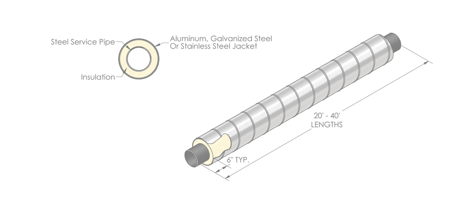


Overview
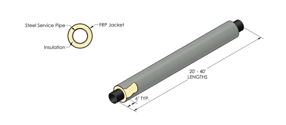
- Application:
- Chilled Water, Condensate, Condenser Water, Heating Hot Water, Petroleum Products, Steam
- Service Pipe:
- Carbon Steel, Stainless Steel
- Insulation:
- Polyurethane Foam
- Temp:
- Up to 250°F (121°C)
- Nom Length:
- 20 Ft. - 40 Ft.
System Specifications
| Pipe Size | Minimal Insulation Thickness | PVC Jacket O.D. | PVC Jacket Wall |
| ½” | 1.76” | 4.50” | .070” |
| ¾” | 1.66” | 4.50” | .070” |
| 1” | 1.53” | 4.50” | .070” |
| 1¼” | 1.35” | 4.50” | .070” |
| 1½” | 1.23” | 4.50” | .070” |
| 2” | 1.81” | 6.14” | .070” |
| 2½” | 1.56” | 6.14” | .070” |
| 3” | 2.25” | 8.16” | .070” |
| 4” | 1.75” | 8.16” | .080” |
| 5” | 1.25” | 8.16” | .080” |
| 6” | 1.69” | 10.20” | .100” |
| 8” | 1.69” | 12.24” | .120” |
| 10” | 1.65” | 14.32” | .140” |
| 12” | 1.47” | 16.00” | .160” |
| Pipe Size | Minimal Insulation Thickness | HDPE Jacket O.D. | HDPE Jacket Wall |
| ½” | 1.66” | 4.50” | .175” |
| ¾” | 1.55” | 4.50” | .175” |
| 1” | 1.42” | 4.50” | .175” |
| 1¼” | 1.25” | 4.50” | .175” |
| 1½” | 1.13” | 4.50” | .175” |
| 2” | 1.93” | 6.63” | .200” |
| 2½” | 1.68” | 6.63” | .200” |
| 3” | 1.37” | 6.63” | .200” |
| 4” | 1.58” | 8.00” | .175” |
| 5” | 1.05” | 8.00” | .175” |
| 6” | 1.51” | 10.00” | .175” |
| 8” | 1.73” | 12.43” | .175” |
| 10” | 1.48” | 14.06” | .175” |
| 12” | 1.39” | 15.87” | .175” |
| 14” | 1.72” | 17.83” | .175” |
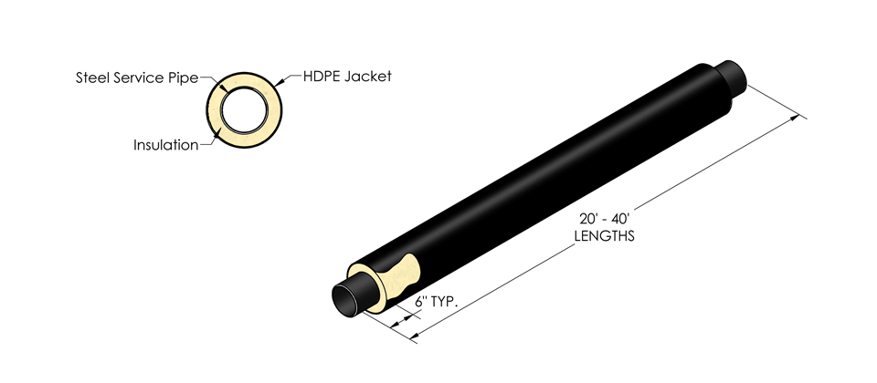
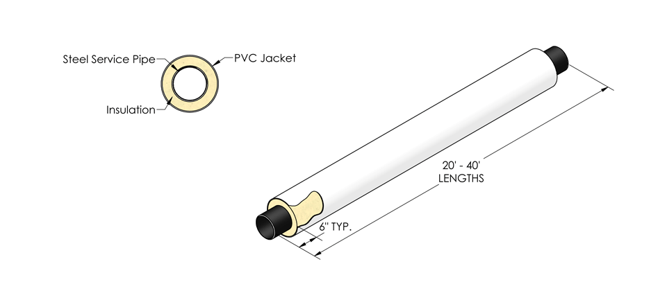
Service Pipe:
Carbon steel service pipe shall be standard weight A53 ERW or A106 seamless beveled for welding. Stainless Steel
piping shall be type 304L or 316L, Sch. 40 or Sch. 80, welded or seamless, to ASTM A312/A312M. Condensate return piping shall be Schedule 80. All joints for pipe 2½” and larger in size shall be butt-welded. Sizes 2” and smaller shall be socket welded. Straight lengths of piping will be supplied with 6” of piping exposed at each end for field joint fabrication. Pipe lengths shall be supplied in 21-42 ft. lengths.
Insulation:*
The insulation shall be foamed in place closed cell polyurethane, completely filling the annular space between
the service pipe and the exterior casing. The insulation shall have the following physical properties:
- Minimum Density (lb./cu. ft.) 2.0 ASTM D-1621
- 90-95 % Closed Cell ASTM D-6226
- “K” Factor BTU/Hr. sq. ft. °F/in. . . .16 ASTM C-591
- Compressive Strength ASTM D-1621
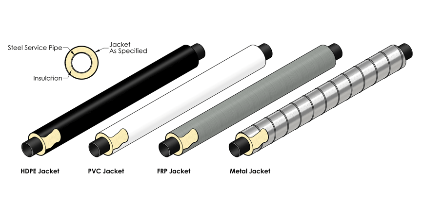
Exterior Jacket:**
The exterior casing shall be one of the following:
(1) High Density Polyethylene (H.D.P.E.) to ASTM D-3350-12, with the following physical properties:
- ASTM D-3350…Minimum Cell Classification Grade PE 334363C
- ASTM D-638…Ultimate Elongation 200%
- ASTM D-638…Tensile Yield Strength 2500 psi
(2) Seamless, extruded white PVC Type 1, Grade 1 Class 12454-B per ASTM D-1784
No polyethylene tape casings will be allowed.
Sub-Assemblies:
All fittings, anchors, end seals, and other accessories shall be prefabricated or field fabricated dependent upon engineer’s option and/or site conditions. Fittings 2½” and larger to be butt weld conforming to ASTM A234 WPB & ASME B 16.9. Fittings 2” and smaller to be socket weld conforming to ASTM B 16.11. All factory prefabricated fittings shall be welded to ANSI B 31.1.
Field Joints:
After welding and hydrostatic testing, HDPE jackets will use polyurethane foam, a heat shrinkable sleeve, and an HDPE rockshield. PVC jacketed straight field joints will use polyurethane foam, a PVC sleeve, and pressure sensitive tape.
Expansion/Contraction Compensation:
Expansion and contraction within the piping system shall be accommodated with factory prefabricated internal expansion elbows, z-bends, expansion loops, and anchors specifically designed for each application. External expansion compensation provided with the use of flexible foam bolsters.
Installation:
No Piping shall be installed in standing water. Trenches shall be maintained dry until final field closure is complete. The installing contractor shall handle the piping system in accordance with the directions furnished by the manufacturer and as approved by the architect and engineer. The service piping shall be hydrostatically tested to 1-1/2 times the operating pressure, or as specified in the contract documents. The test shall be maintained for a minimum time of 1 hour. EXERCISE DUE CARE WHEN INSTALLING AND TESTING THE PIPING SYSTEM. DO NOT TEST WITH AIR OR GAS.
Backfill:
A 6-inch layer of sand or fine gravel, less than ½” in diameter, shall be placed and tamped in the trench to provide uniform bedding for the Steel 250 system. Once the system is in place, the trenches shall be carefully backfilled with similar material and hand tamped in 6” layers until a minimum of 12” above the top of the preinsulated pipe has been achieved. The remainder of the backfill shall be void of rocks, frozen earth and foreign material. The trench shall be compacted to comply with H-20 Highway loading.
Accessories:
- Heat Tracing
- Leak Detection
System Options:
- *Insulation thickness will vary depending on the type of insulation specified and the operating temperature.
- **Optional metallic casings for above grade include Galvanized, Aluminum Stainless Steel (coated steel available).
- **Optional non-metallic casings for below grade offered include, Filament Wound FRP.